I will be updating this thread as I work on this project. My plan is to make this a support weapon capable of sustaining 26 rps with 7.4V battery. In hindsight, it might have been better to go with 11.1V with slower gearing for efficiency, but I already committed.
I am not responsible should you decide to follow my methods. It takes a certain level of skill and knowledge and it is advised to use care when working on airsoft guns.
The Gearbox
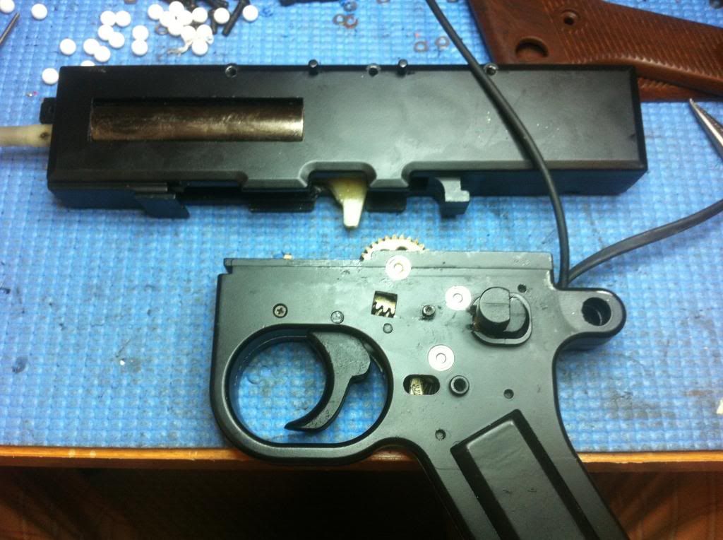
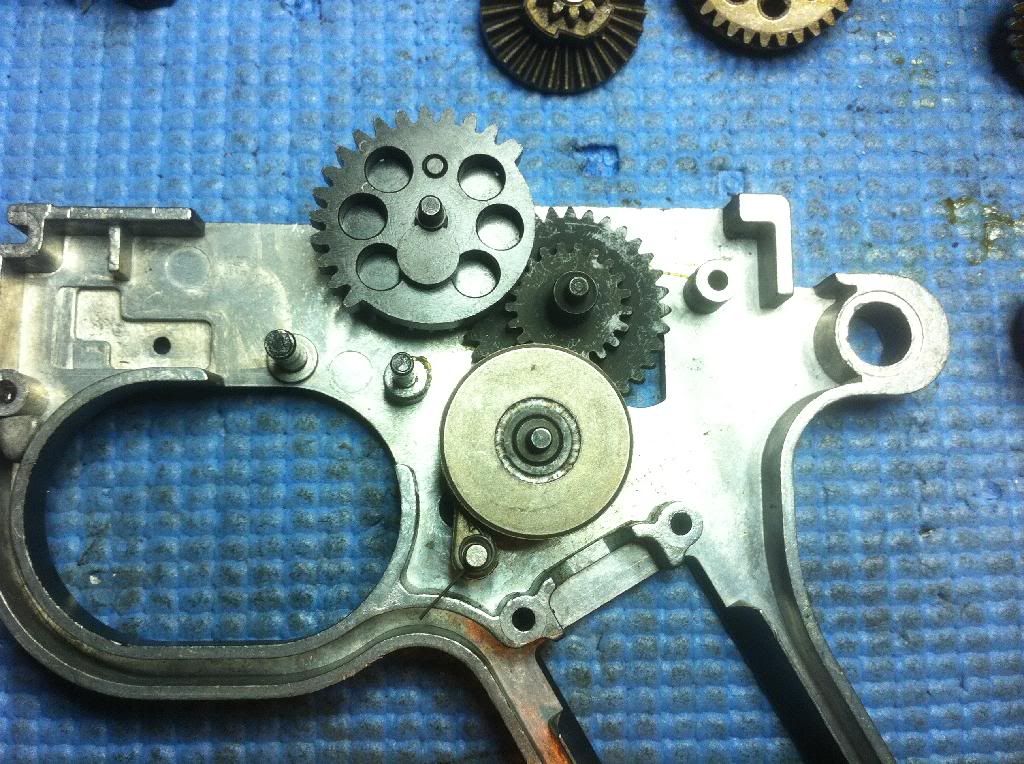
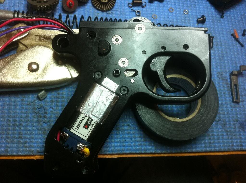
It took me a while to figure out how to remove the gearbox out of the receiver. It turns out the gearbox is a split-type. Once the associated bolts, brackets and QD spring are removed, only the tappet plate pressure keeps them together. Pulling the grip right of the picture allows you to clear the front lip and slide the two halves apart.
*If your QD spring guide doesn't want to come out, there is a trick that might work: Disconnect the battery and release spring tension by releasing the anti-reversal latch (ARL) via the access window hidden behind one of the piston grip. Once the ARL is released, the piston should return to near its resting position (if the spring was compressed to begin with). If you want, you can spin the sector gear a few degrees to clear the piston further (CCW in this picture), while holding back the ARL, if you think it's still partially meshed. You'll have to work against the force of the motor, so take care when doing this. If you are successful in rotating the teeth out of the way, you should be able pull apart the halves by overcoming the tappet plate spring force.
Alternately, you can just dry fire the gun a couple of times and go by feel to see if the piston has gone back to the resting position.
When re-installing the gearbox, make sure the piston is all the way forward and that the sector pickup teeth are spun out of the way.
If you're still having trouble removing the gearbox, this video demo might help:
<<Gearbox Removal>>
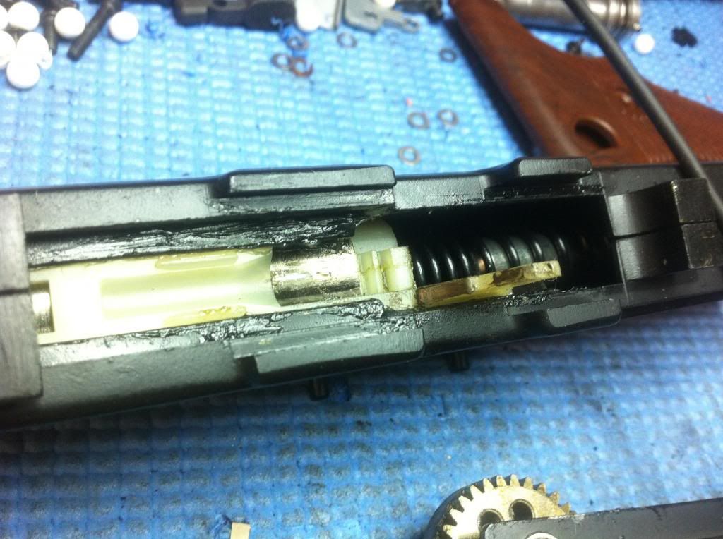
The top part of the gearbox uses T8 torx screws. This is a QD type spring guide similar to the M249, but on mine, it didn't actually come out after multiple attempts until I actually took the gearbox apart. I think the spring guide was getting caught inside of the gearbox.
It is worth noting that the spacing between the piston and the spring guide is about 1 cm shorter than standard gear boxes. Thanks for this info from Rafter_Man.
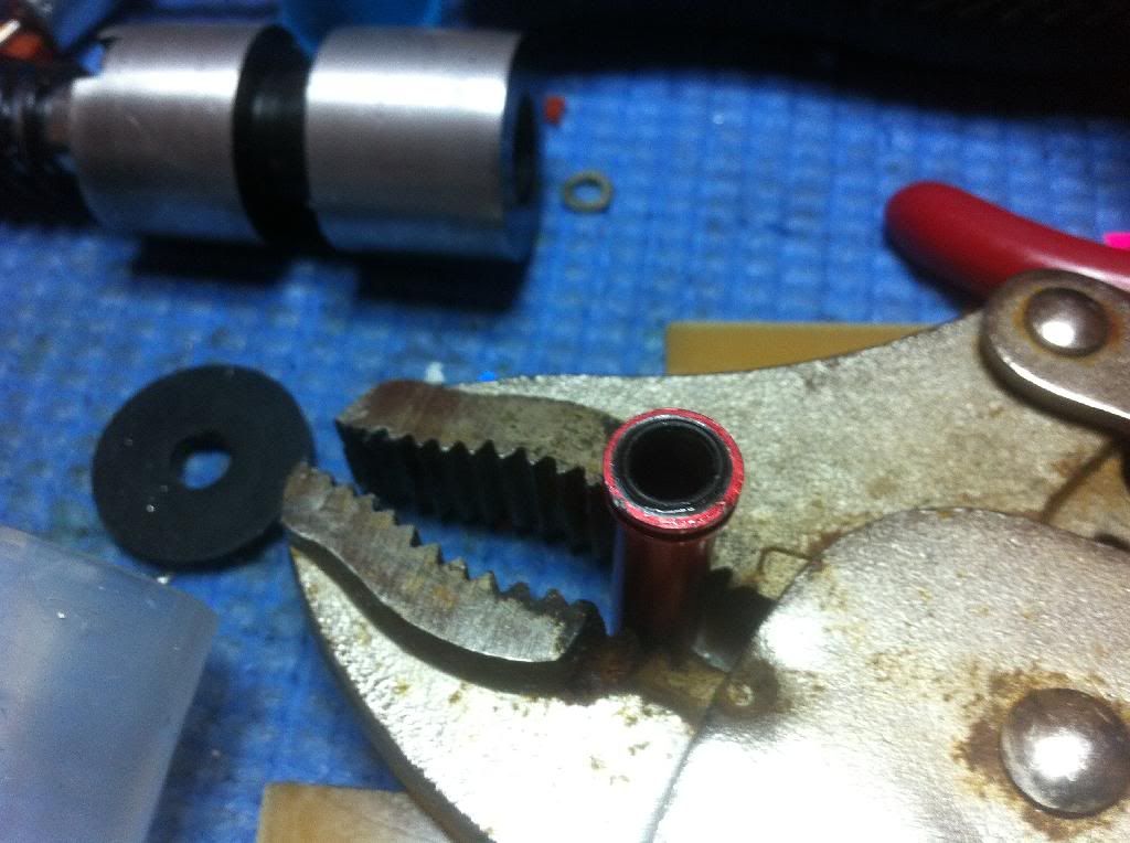
The QD spring didn't work for me because the spring guide was too big. With some 400 grit sand paper and a hand drill, I sanded it down enough for it to move freely even after the gearbox is tightened.
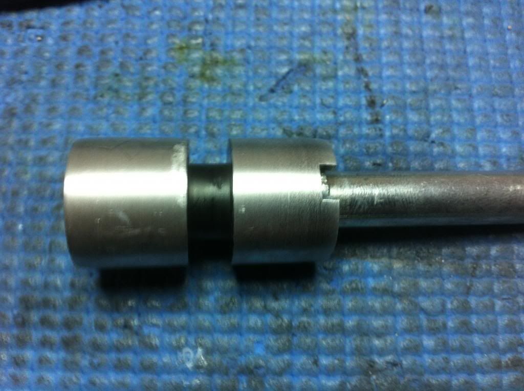
The cylinder head is not a standard V2 one. The cylinder head nozzle is 21.3 mm long. The nozzle itself is also longer at 29 mm. It seems to have some sort of taper design and I could feel resistance as the nozzle is moved towards the cylinder head. I'm not sure what the purpose of this is because it seems to hinder tappet plate movement. There is some sort of padding, 2.7 mm deep, which feels a lot firmer than my 70 sorbo.
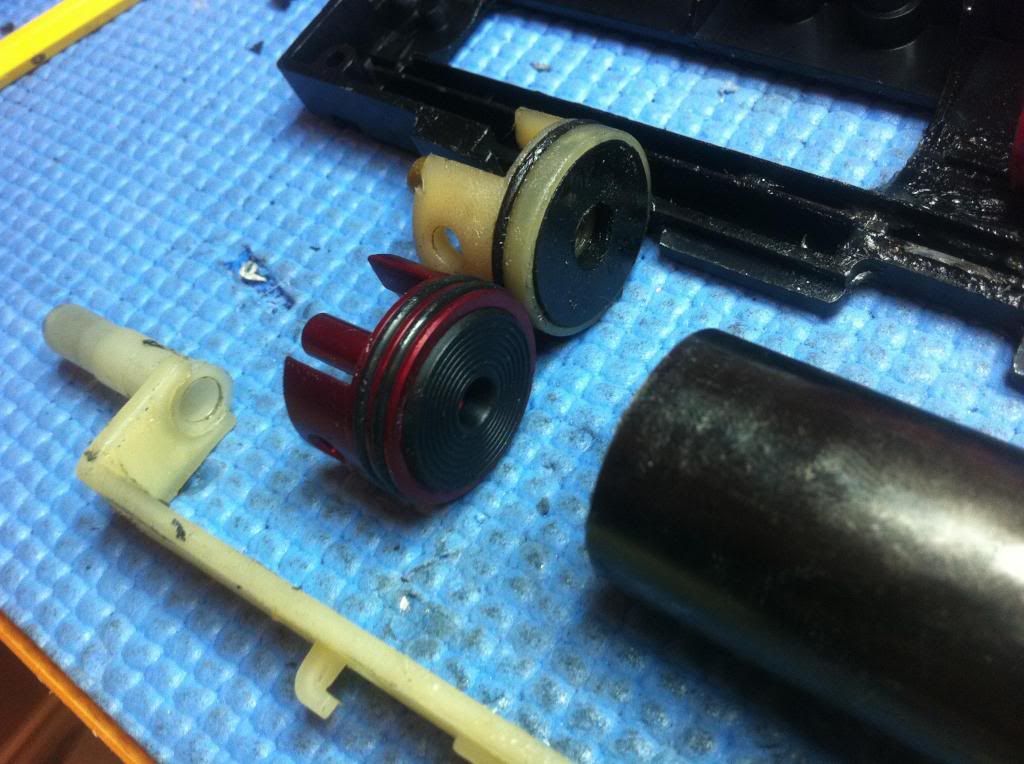
The stock piston head / cylinder combo has virtually zero compression. I can move the piston in and out of the cylinder with my finger sealing the cylinder head, with only slight resistance. Swapping in a new piston/piston head immediately improves compression.
Here are some measurements I took with a digital caliper:
Cylinder diameter: 23.85 mm
Approximate distance from the middle of the piston head o-ring to the end of the cylinder: 6.26 mm
Length taken up by Guarder cylinder head and 3/16" sorbo: 11.26 mm
Total cylinder length: 70.73 mm
With my setup, after the AOE correction, the cylinder to barrel volume ratio is about
1.21 with the stock 660 mm barrel. By shortening the stock barrel to 470 mm, I've lowered the ratio to about 1.7.
From the top: V2, stock, V3 Marui Aug
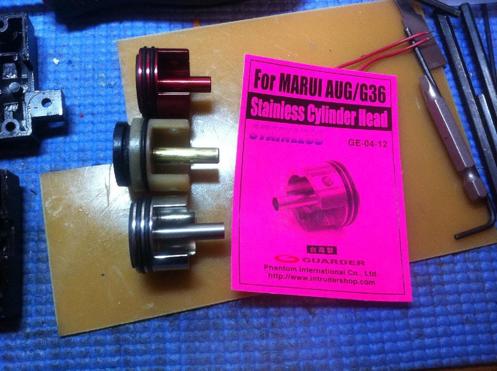
I had to cut off the extra material on the cylinder head in order for it to fit. This will not be necessary if you can find a V2 cylinder head with extra long tip. At this point, I'm not sure if the extra long long even serves any function. I used a cylinder head with a long tip just to be on the safe side.
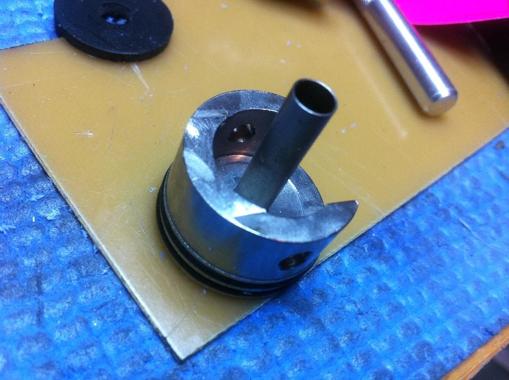
Note that the Guarder V3 Marui Aug cylinder head shows a bit of the first o-ring when installed into the gearbox. Compression was still 100% and it has another o-ring, so I didn't really think it mattered. No action was taken to correct this. I could have probably enlarged the window a bit to allow the cylinder to move up more to cover the o-ring and at the same time become compatible with standard cylinders, but I didn't think this is necessary at this point.
A problem I noticed with the stock cylinder is that it is not seated very straight. I noticed this when trying to improve efficiency and felt resistance at the end of the travel with the piston. I fixed it by removing material from the gearbox on one side and adding tape on the other.
AOE is at about 11:30 position.
According to this database, the PTS Masada nozzle might work? (Now, confirmed!)
http://forums.airsoftmechanics.com/i...p?topic=7734.0
http://forums.airsoftmechanics.com/i...?topic=10851.0
At this time, I wasn't able to find any PTS Masada o-ring nozzles, so I added an o-ring to this one made by Matrix. The seal improved, but still not 100%. I will probably change it to a proper o-ring nozzle later when I get a chance.
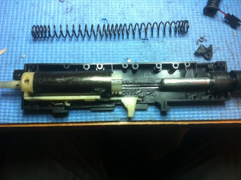
The tappet plate looks like a standard V2. When comparing with the SHS V2 tappet plate, the fin on the stock unit is more progressive.
One difference I did notice is that the spring post for the tappet plate is a few mm closer than your standard V2. This would explain why the stock spring is so much stronger. Testing with a stock V2 tappet spring doesn't seem to make a difference. I opt for the softer, V2 spring because it puts less load on the motor.
I did notice that the channel for the tappet is not very straight, especially at the front end. I had to sand it down flat so that there's less resistance when moving the tappet plate.
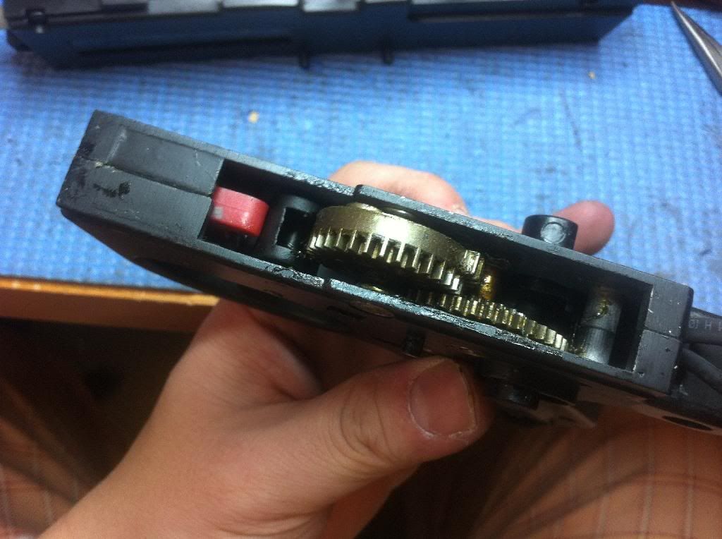
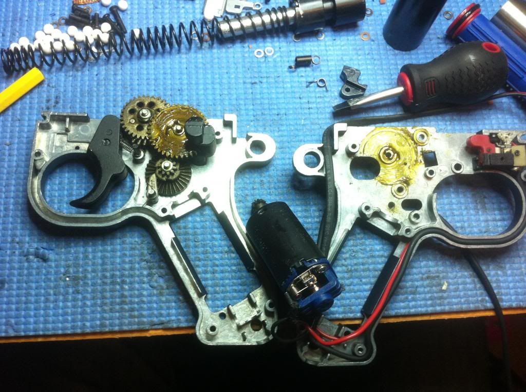
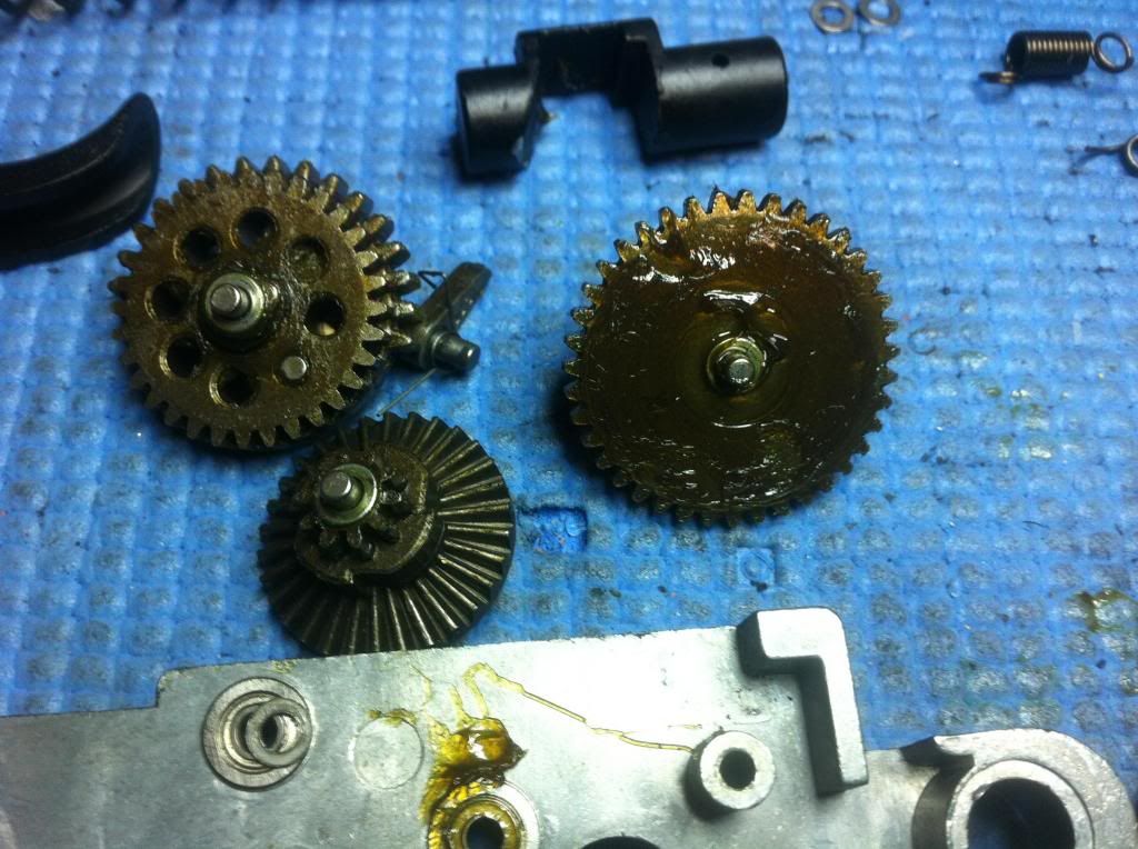
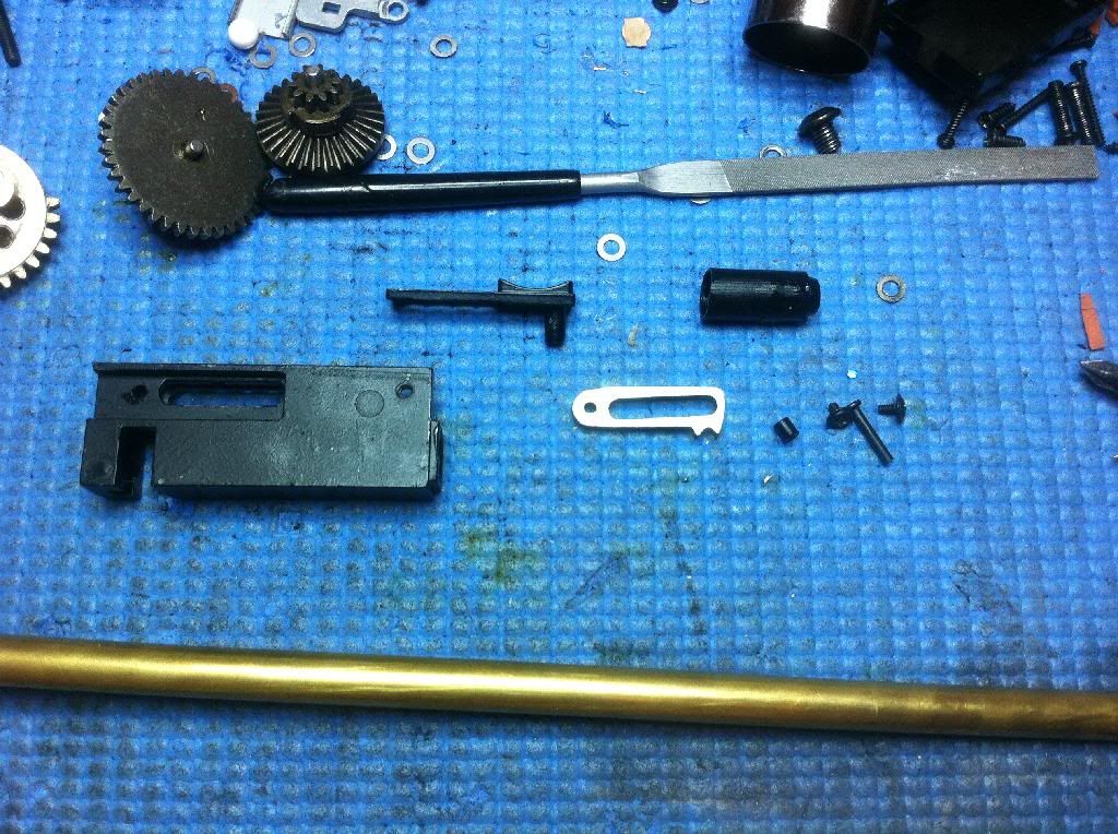
The lower gearbox is also held by T8 torx screws. There seems to be almost no grease on the bevel gear. No motor height adjustment mechanism can be found either. Luckily, the stock pinion position is pretty spot-on. When I put my JG blue in, I had to adjust the position of the pinion to get a proper bevel mesh. I also shortened the motor posts because they were a bit too close to the gearbox for my liking. When trying to shim the bevel to the pinion, I noticed that the cage doesn't keep the motor from moving. I wrapped aluminum tape from the motor to take up the slack. I later changed to a Lonex motor and that motor did not have issues with slack or motor posts.
The gears all say "X" on them.
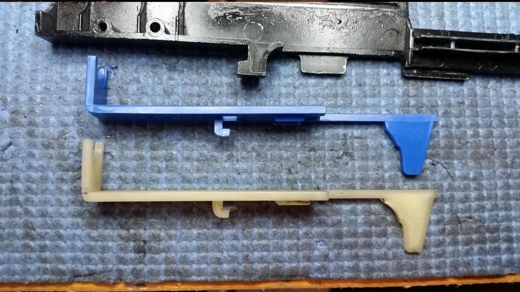
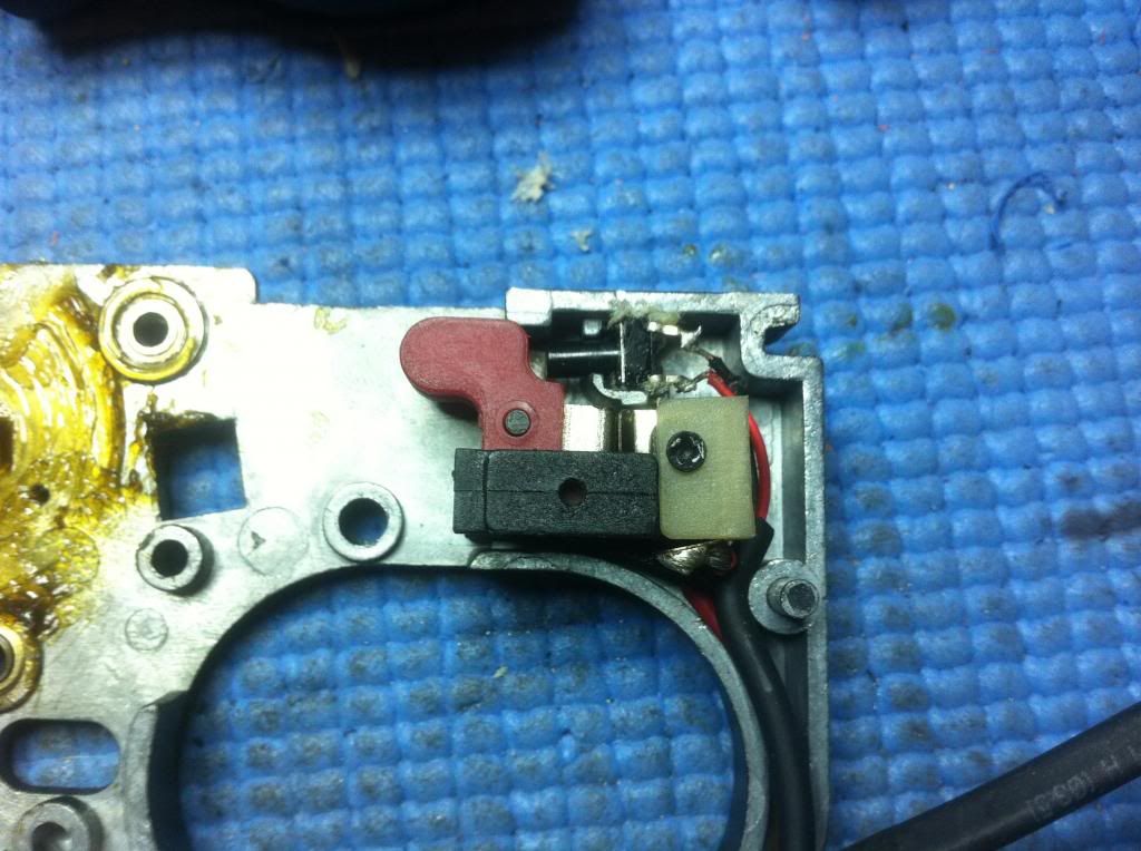
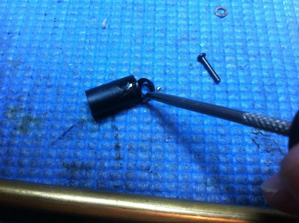
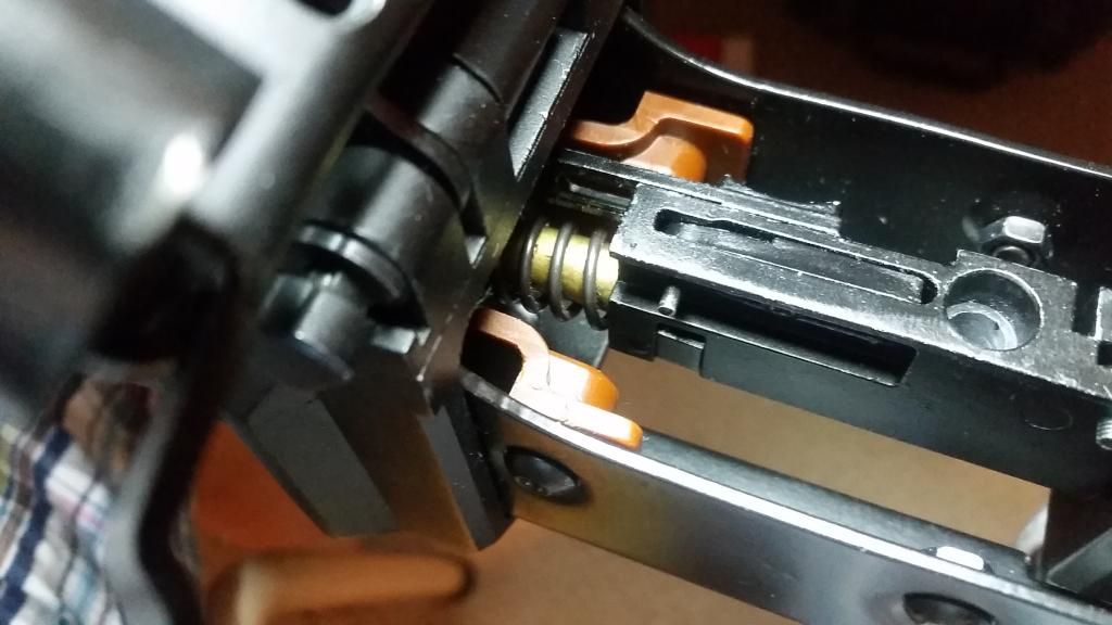
Here is the trigger trolley. It's one unit with a return spring inside. The switch on top activates the motor on the drum. The switch seem to have been glued in place and is very fragile. Trying to pull it out with my pliers cracked the switch. I later pried it out with a pick instead. The button also feels very loose. Good thing I won't be needing it since I'm wiring it to the main battery. The contacts are close together so it's possible to pull the trigger slightly to shoot but not activate the feeder. Bending the contacts back should fix this problem on a stock unit.
The SC 10.44 SSG set seems to fit in the gearbox half, which should suggest that it will work with other V2 gear sets. (Note: The gears are not supposed to be installed this way, I just put them there to test axle spacing.)
A 3/16" sorbo pad seems to put this SHS piston and Guarder piston head at the right AoE.
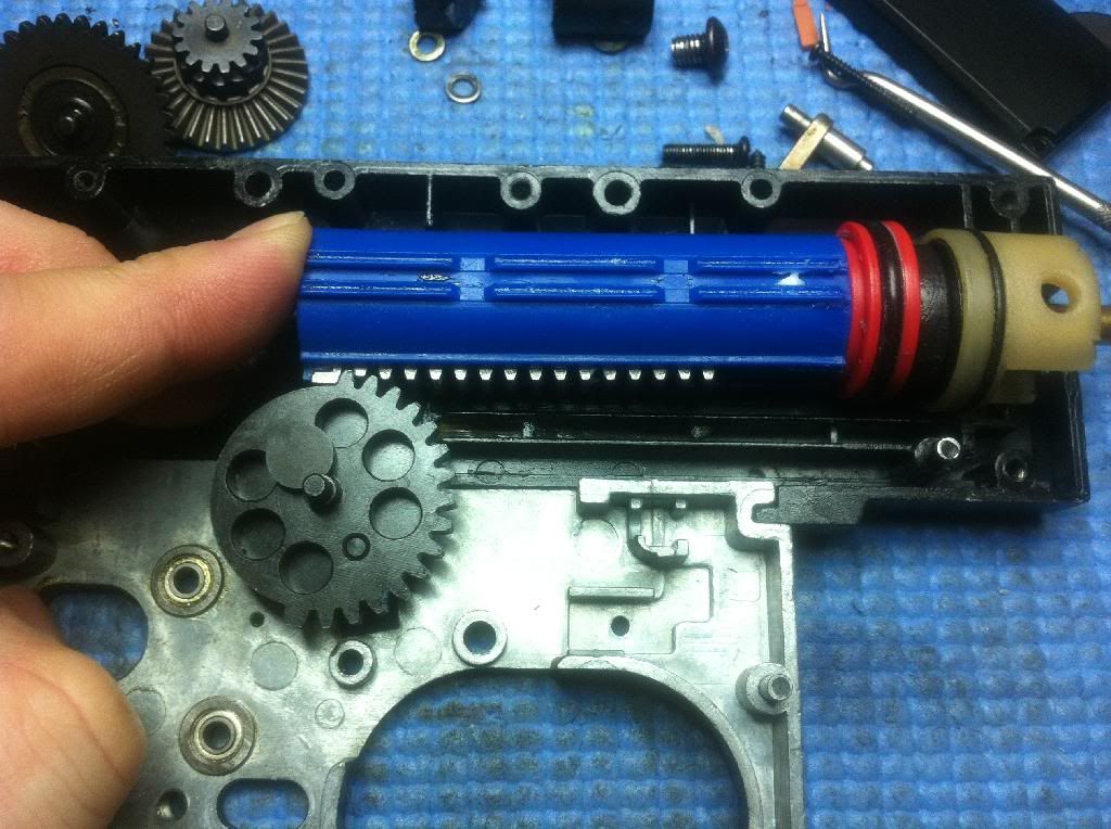
The piston seems to sit pretty low. I had to shave off some of the reinforcement on the SHS pick-up tooth to allow clearance for the SC SSG 10.44 sector gear. I also had to remove the 2nd tooth and most of the 3rd tooth.
(I used the spring when testing the actual AoE job.)
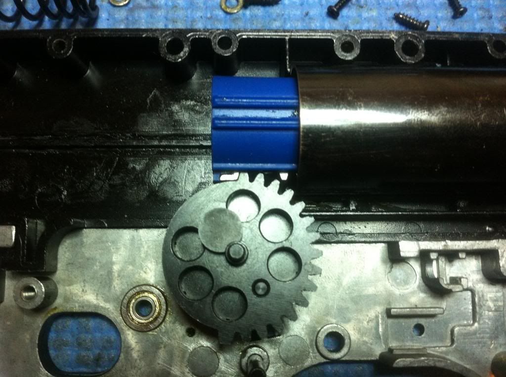
SC SSG 10.44 gears fitted in the gearbox. The ARL is not shown in this picture. Notice that handy little window that allows you to release the ARL without taking the GB apart.
Note: The safety is a combination of a trigger block and spur gear block. I think the actual safety button used to slide over the spur gear's teeth to prevent it from spinning. Since, my SC gear set has a smaller spur gear, this part of the safety is no longer there.
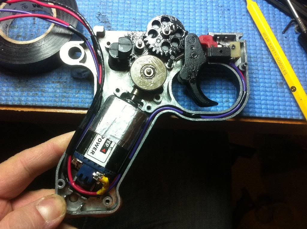
Notice the aluminium tape I used at the top and around the motor to reduce play. This made satisfactory shimming possible.
 The Barrel GroupThis section is under review. Modify at your own risk.
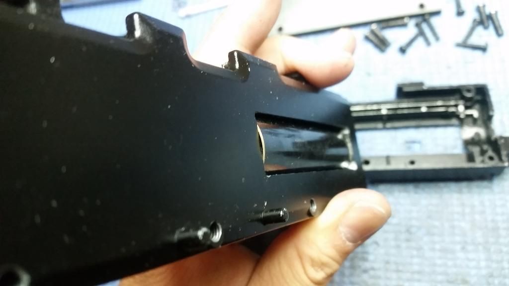
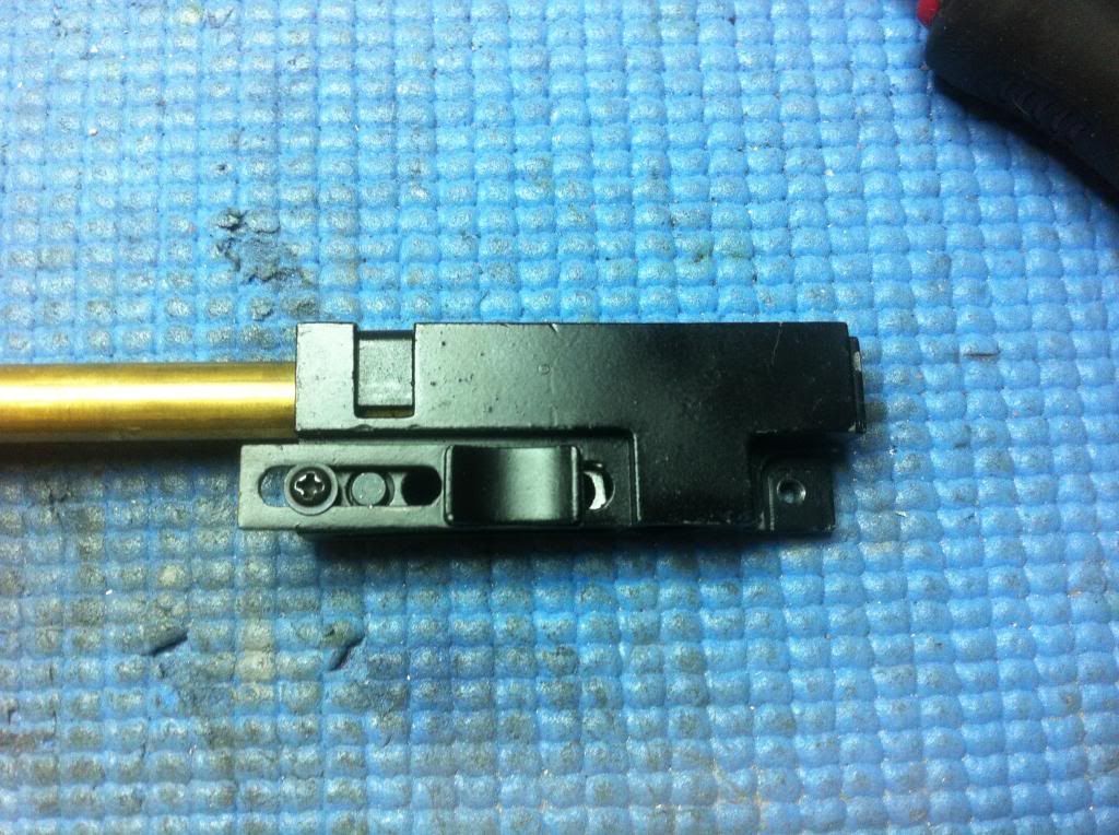
This is the metal hop up chamber. It has a sliding mechanism that adjusts hop. Does anyone recognize this from another gun? I would like to know a backup source in case this breaks.
The barrel is about 660 mm long. Looks like a standard AEG barrel. There's a groove cut about an inch away from the muzzle. I'm not sure what it's for, but I'm not particularly interested in making this gun accurate (volume of fire over precision), so I didn't bother with the details. It seems like a good place for a stabilizer o-ring.
I also noticed that there was no barrel stabilizer ring at the chamber. I'm not sure if I've lost it, but I slipped on one that came with my Lonex bucking, and it didn't really want to stay. It was too loose on the barrel such that it is free to slide out on its own, so really it does nothing to stabilize the barrel.
Inner diameter measured at near the muzzle is approximately 6.15 mm. It's difficult to measure bore diameter with the caliper, this is the best measurement I took.
Later I discovered that the ring was likely left out on purpose. More on this later.
The I cracked the holding clip for the barrel while trying to remove it. I'm not sure if this is the part's fault -- I'm never good at removing these... The bucking also ripped while I was trying to remove it.
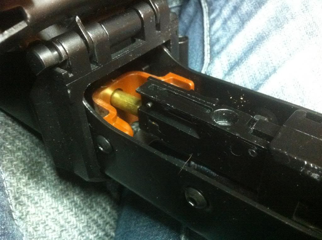
Trying to install the upgraded gearbox in the gun along with the hop-up, I ran into a problem. It seems the stock design has a lot of give around the nozzle, but when I changed it from the stock, plastic, stepped nozzle to a straight, metal nozzle, it interferes with the chamber in such a way that it's difficult to cycle the tappet.
I highly recommend that you check for this interference before shooting. You can do so by cycling the tappet plate with the barrel group installed.
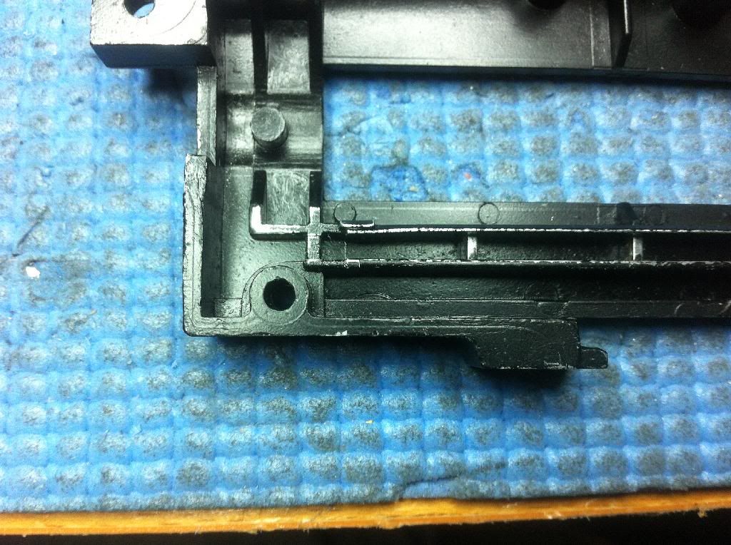
I looked into this problem and this is what I've found: The chamber is aligned to the gearbox via a square cut-out on the front of the gearbox. In theory, this is great, as the chamber is perfectly squared to the gearbox. The problem is, the outer barrel and gearbox alignment is not good. When you try to force the install, the result is that the loading end of the inner barrel will push down on the chamber, putting pressure on it and deflecting it slightly in the nozzle 's way, causing it to hit the top part of the chamber. I believe the brass barrel ring was left out for this reason, to allow the inner barrel to have some range of movement. With the brass ring in, the install became even more difficult.
To fix this problem, you can:
1. Raise/angle the outer barrel up slightly to relieve pressure on the chamber. You can do so by modifying around this brown plastic piece, which secures the back end of the outer barrel.
2. Adjust gearbox alignment by slotting the screw holes for the gearbox halves. I didn't do this because the weight of the whole gun will be loaded on the gearbox and I didn't want any chance of movement created by the slotting. Someone with metal working skills may be able to do this successfully. As a matter of fact, the stock receiver seems to be slightly slotted already, possibly done at the factory in an attempt to allow the tappet/nozzle to cycle.
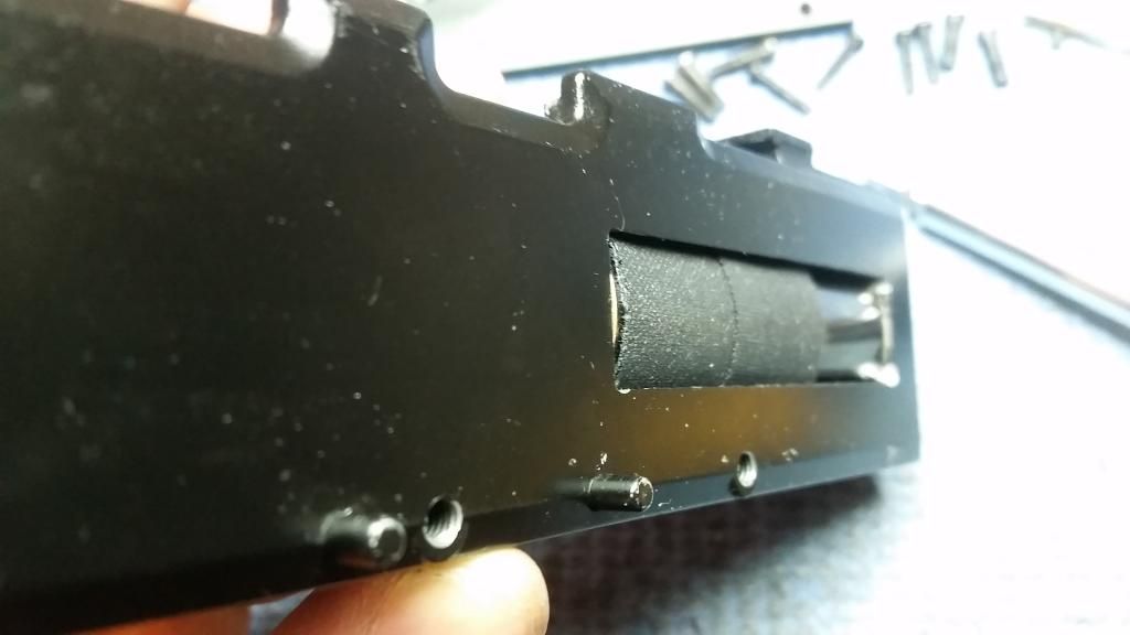
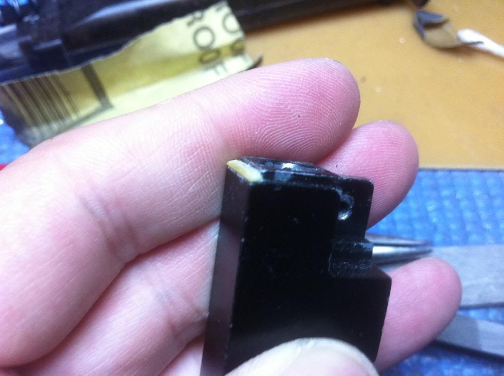
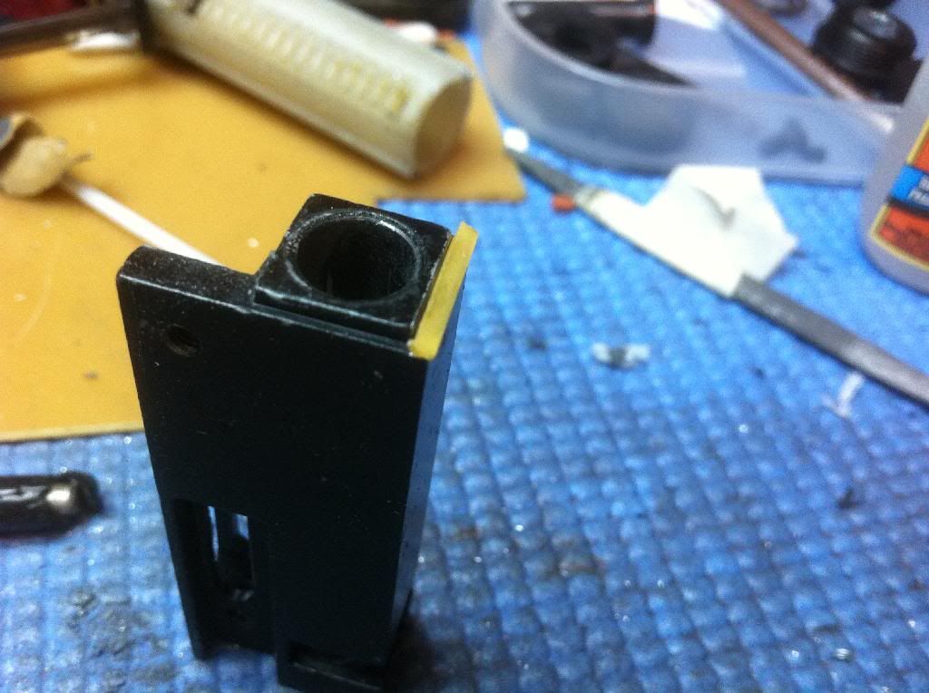
3. What I did to fix this problem was shimming the bottom of the chamber to force alignment of the nozzle with the chamber. The inner barrel will try to force the chamber to bend downwards, but the shimming will force the chamber to stay in proper alignment with the nozzle. In my case, I happened to have some unused PCB board lying around, which I glued onto the chamber, but in theory you could use any rigid material.
*Note: Allowing the inner barrel to be at a different angle to the chamber may* cause feeding issues or air leaks depending on the extend of the modifications and bucking type. Be sure to fully test your modification, for whichever one you choose. As said before, accuracy is not my top priority, so the fact that the gun fed was good enough for me.
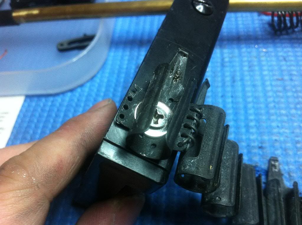
**Note: There is a screw that attaches the chamber to the gearbox. DO NOT over-tighten this screw as it will also cause interference with the nozzle.
***Note: Whichever method you choose, check the loading dock/platform as it sits directly on top of the hop chamber.
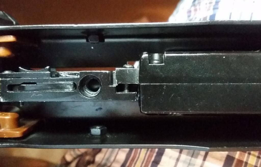
Thanks to duggan69, I've been informed that the later version of this AEG comes with a spring that pushes the chamber against the gearbox. I investigated and noticed how this may be beneficial. The horizontal screw acts as a locator to line the two pieces up, but it doesn't do a very good job since it doesn't prevent rotation in all planes. Over-tightening it causes mis-alignment issues, so that's not a good solution. Having the spring there helps to insure that the nozzle and bucking are at a consistent distance apart. I cut a small section of an sniper spring and installed it around the inner barrel, in front of the hop up.
Screw loosened to demonstrate point.
 The Drum
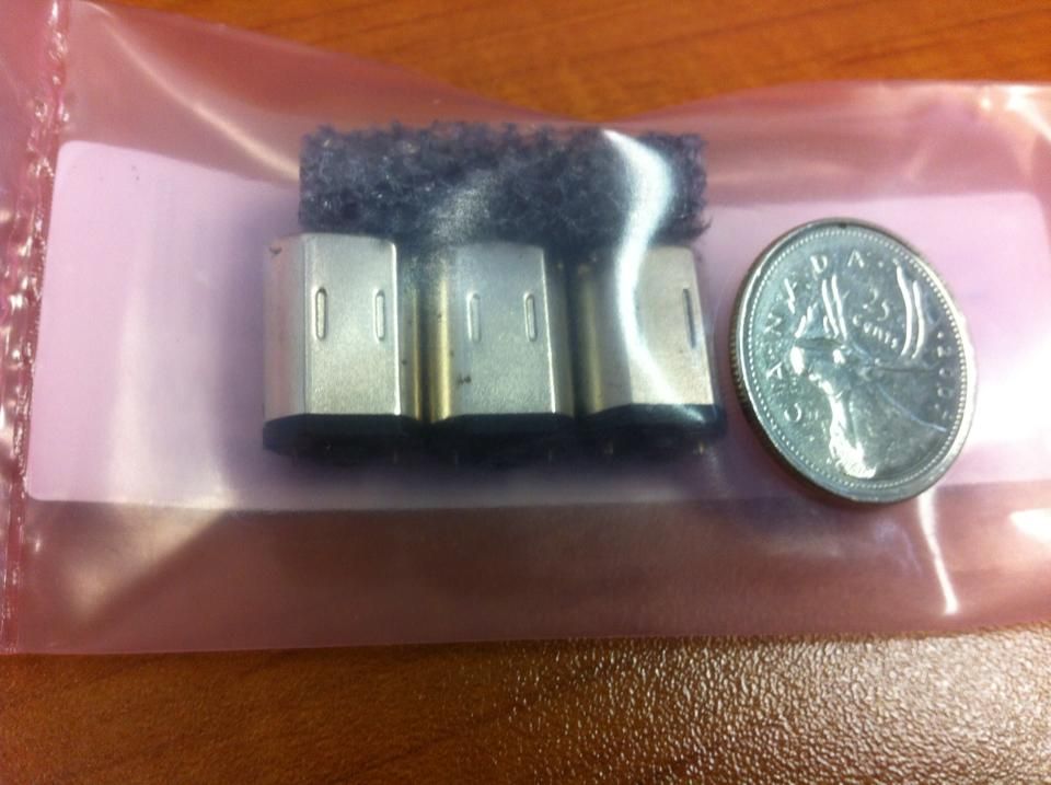
Drum motor upgraded with Virtuabotix N20 Micro:
http://youtu.be/tju5xhqdtq4
I'm quite happy with the way it turned out. By my calculations, it is now feeding at about 24+ bps with 4 AA batteries, as supposed to the ~15 bps from the stock one. The bb's in this video were KSC 0.30 g's. In this experiment, I was using the stock battery holder containing 4 AA batteries. I measured the voltage to be about 6.36 V, using a multimeter. The current of the new motor was ranging from 0.10 A to 0.15 A.
Motor:
https://www.virtuabotix.com/product/...3-7v-25000rpm/
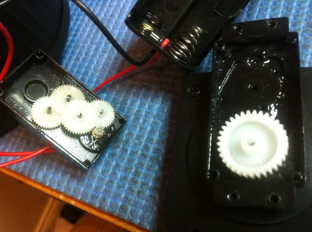
Inside of the drum's gearbox.
I've added a mom-on switch to the drum so I can "prime" the feed tube without dry-firing. It is a SPDT switch. Why SPDT? I used it isolate the gun's circuitry so that pressing the priming switch won't cause the gun to cycle. I'm sure there are simpler and more elegant ways of achieving this but my knowledge is limited in the subject. I also bought this switch by accident, which worked out pretty well in the end.
Here's a simple schematic of the wiring design I used. The push button switch is normally connected the gun's circuit, but when you push the button, it disconnects from the gun's circuit to prevent the running of the gun motor.
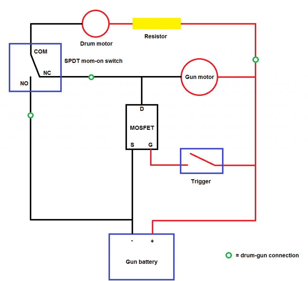
Note that when using my design, touching certain connectors will cause the gun to fire. That is why I "gendered" the connectors and place the connectors in the following manner(put distance between the two male connectors on the gun's side and insulate the female.). Care should always be taken whenever the main battery is connected. The connectors I used are 2.0 mm bullet connectors.
Since, the drum runs whenever I pull the trigger, I wanted to synchronize the feed rate of the drum with the rof of the gun as much as I can. I believe doing so gives the best efficiency*. Slow feed rate limits rof, and the gearbox would be cycling more than necessary, adding wear. If the feed rate is too high, the gun will not be able to keep up and it will only shoot at the maximum cyclic rate of the gearbox. This will also add unnecessary stress on the
drum's motor since the gun will not remove bb's faster than the drum push bb's into the nozzle, causing a momentary stall before the nozzle moves out of the way and allows the next bb to chamber.
*I realize the gun's gearbox works in cycles and it doesn't remove bb's from the chamber at a constant rate (but rather like a pulse). I still stand by my theory that matching the rates yields a good balance of stress vs. performance.
I used a series of 10W resistors adding to 6.5 Ohms (specified), which resulted at exactly the target of 26 bps.
Here are the results of the various combinations of resistors that I tested with:
7 Ohms = 25 bps
6.5 Ohms = 26 bps
6 Ohms = 27.7 bps
3.5 Ohms = 28.7 bps
I plotted the four data points on a graph but it didn't really produce anything concrete. I got to my target before I needed to use that much data. The plot almost resembles a logarithmic function. With the resistors in series, the current draw went up to around 0.19 A.
***
Why not a voltage regulator? A voltage regulator is a great idea since it supplies the feed motor for the exact voltage that it needs for a certain speed but after doing some research on ASM, I believe that it is better to use resistors since the voltage of the main battery will drop along with rate of fire as it is being used. It is believed that both the rate of fire of the gun and feed rate will drop similarly together.
If you want to use a voltage regulator, here are some part numbers as suggested by
philsaudio on ASM:
Quote:
LM 7806 6 volt positive regulator
LM 7808 8 volt positive regulator
3 pin TO220 positive regulators under a buck.
|
***
To help speed up the testing process. I used an old brass barrel, plugged one end and counted how many bb's could fit in it. In my case, that's 74. I ran the drum for a given amount of time, feeding the bb's into an empty box. At the end, I counted how many times I could fill this barrel, plus whatever's left.
For example. IF:
Ran the drum for 9.56 seconds
Filled the barrel 3 times
Still had 15 bb's left in the box
74 x 3 + 15 = 237 bb's
237 / 9.56 = 24.5 bps
The drum was feeding at an average of 24.5 bb's per second. Beats counting bb's 237 times.

This method is confirmed by chrono testing with the gun.
Hint* If you just short of a full barrel, you could always count how many more it takes to fill the barrel and subtract. Example:
My barrel is not full. Adding 15 more bb's makes it full --> 74 - 15 = 59 bb's in the barrel.
 Others
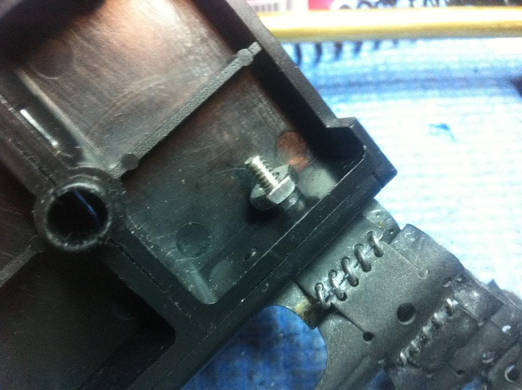
This is the feed adapter block. I got an extra long screw, washer, and nut to secure this empty belt. I used a 6-32 thread screw, which seemed a bit loose but I wasn't able to find anything else that fits, as 8-32 was too big. The nut seems to do the job of holding things down.
NOTE* Someone kindly pointed out that I had the links on backwards! They are installed incorrectly in the pictures below. I will update the pictures when I get a chance to fix this.
Sling - The sling attaches to the piston grip at one end. Make sure you get the late production model, meant for MG42. The early production ones are too narrow to fit on the grip.
Additional Notes
Quote:
Originally Posted by Nailcake

Hello,
I just registered to say a few things;
First I should thank you for this thread, it is the only review I could find on this MG(I own this one myself obviously). I had to change the spring, but since the center guide is stuck in the upper part of the gearbox I had to open it. I got stuck at one point and was only able to continue when I found this thread and learnt about the little spring which you mentioned in the pistolgrip.
Secondly, the one I have is the AGM MG42, which is actually the same gun from the same factory as the S&T/Matrix MG42, just with a different brand on the box. I actually wanted to buy the gun from Evike, but then they decided not to ship abroad.
Unaltered the gun shoots 420fps, too much for fields around here(Belgium).
Also, be careful with the externals, they are rather fragile. The feedingtray on mine arrived with damaged hooks and had to be replaced(now an expensive hardened steel feeding tray with a ten year warantee on it). The aluminium in which the gun is made is flimsy and bends quickly.
I havent been able to take it to a game myself but have already heard from other users about a number of smaller problems with this gun, like batteries in the drummag loosening and the mag no longer feeding when firing on the move because of it.
I hope you dont mind digging here for this purpose.
|
Quote:
Originally Posted by KenTsui
Thanks for adding extra information. I'll add this quote to the bottom of my review for others to see if you don't mind.  I will also update my title as I remember the AGM thing in the WW2 thread, according to a trusted source.
I also had a problem with the feeding tray hooks. They were too far apart and did not allow a solid mounting of the drum. I took a risk and bent them closer together. Thankfully, it did not break off, but you are right, all the metal parts feel weak. |